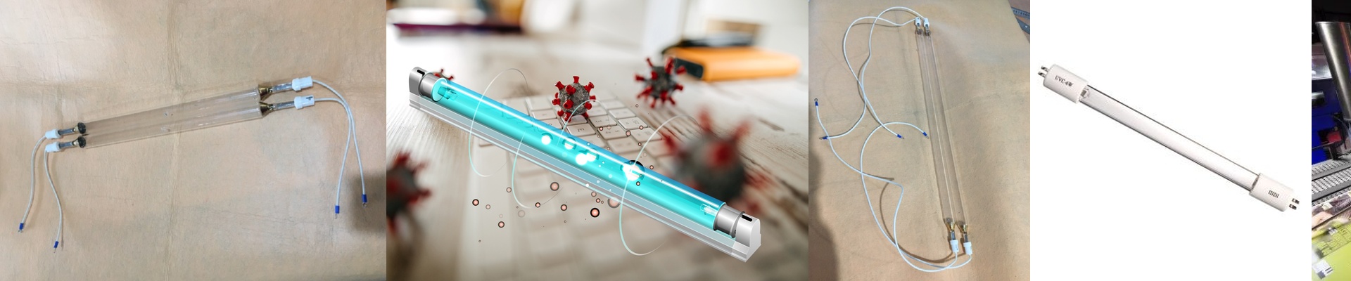
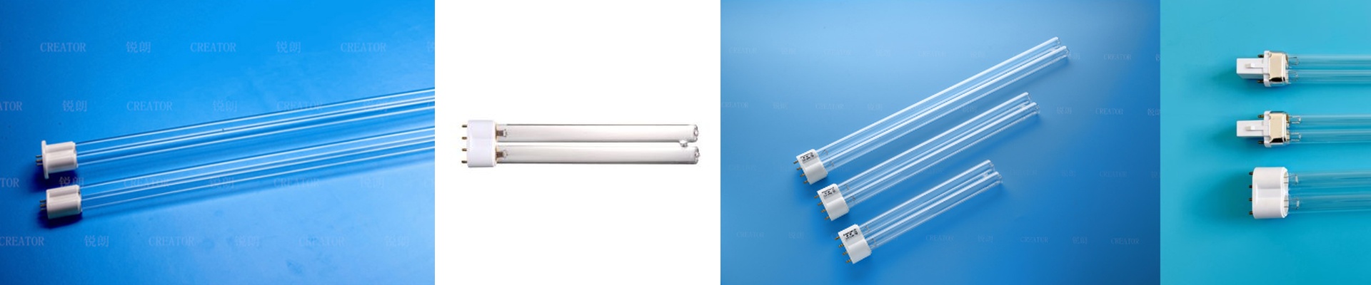
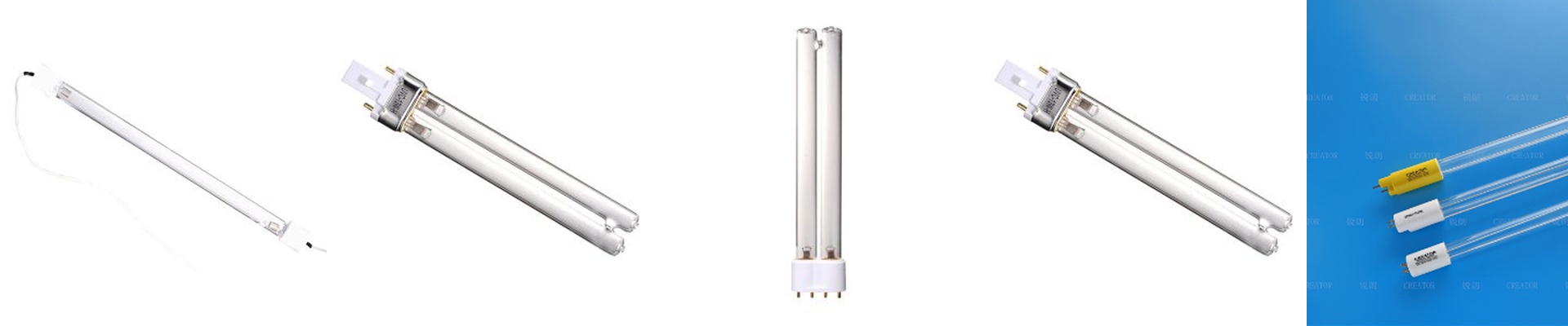
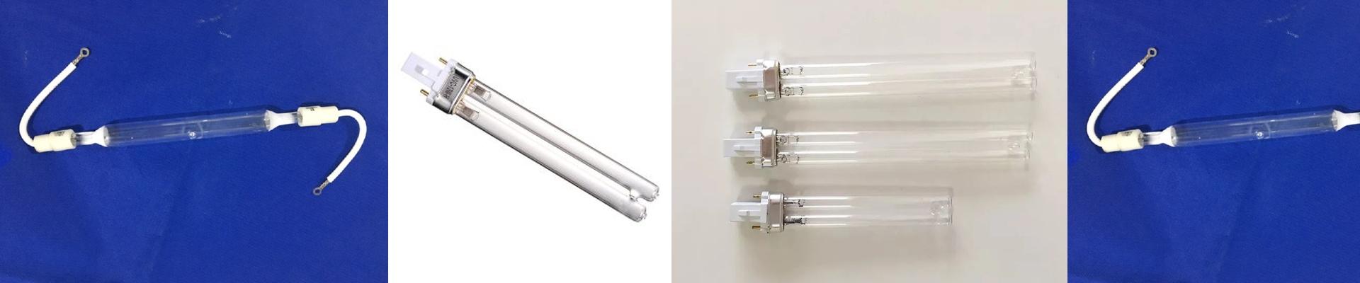
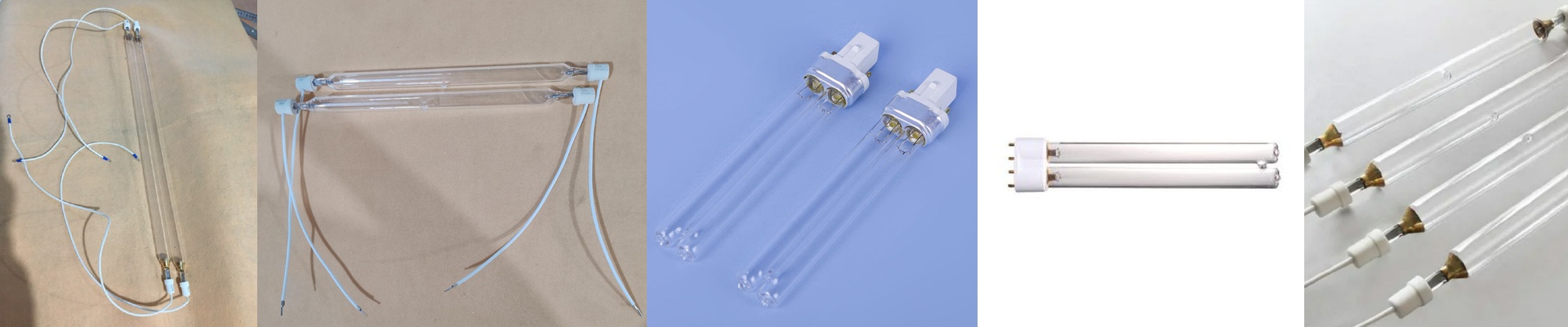
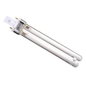
On the PCB line, the solder mask step is where you prove you can handle fine features. Run 50 μm traces and 75 μm dams, and under-cure leaves the mask tacky. Over-cure makes it brittle and hurts adhesion. What controls both is the photon flux you deliver, and it has to stay steady through the entire dwell. What matters under the hood A constant current UV lamp power supply holds lamp current, not voltage. That keeps the arc stable as mercury vapor impedance shifts during warm-up and as the lamp ages. You hold spectral output and peak irradiance, so the energy density at the substrate stays repeatable. Match the lamp spectrum to the photoinitiator package. Hit 365 nm for deep through-cure on opaque mask. Use 385–405 nm when you need surface speed and less yellowing. Spec the arc length to match the print width, run a dichroic-coated reflector for tight spectral control, and stick with ozone-free quartz envelopes to keep the workspace clean. Why this works in solder mask Constant current prevents the UV dip you get as the lamp heats. The first sheet and the thousandth come out the same. Cross-linking stays consistent between fine lines, and adhesion holds up through cross-hatch and thermal stress tests. You can run faster on press without chasing cure. Lamp life stretches because current is regulated against impedance drift. Energy use drops, too, since the supply delivers only the current needed, not extra voltage that just turns into heat. The details that keep you out of trouble Install with a spectroradiometer, set irradiance at the web, and lock the setpoint. Confirm compatibility with your press interface and the lamp ignition sequence. Size the supply for the full arc length, or you’ll get under-cure at the ends. Plan for warm-up. Spectral output won’t settle immediately, so schedule changeovers accordingly.